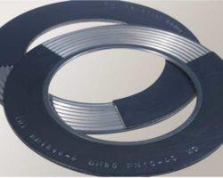
Corrugated Metal Gaskets
The IDT-corrugated metal gaskets consist of a corrugated stainless steel carrier with a height of s = 1.5 mm and a graphite layer of 0.8 mm on both sides. Carrier profile, thickness and density of the layer are adjusted in such a way that a peak overlap of 0.1 to 0.2 mm is ensured in tensioned condition at standard compression and therefore only a very low diffusion cross-section is present. Furthermore, the non-metallic material is very highly compressed in these areas.
A partition of 3 to 4 mm, a sheet thickness of 0.5 and a non-metallic layer thickness of 0.8 mm has proven to be the ideal design and is used as a standard by established plant operators. The IDT-corrugated ring is manufactured across all nominal widths with a partition of 3 mm. If the corrugated ring is partitioned too much, then it loses in strength and has the effect that the proper function could not be achieved or could not be achieved fully and that that the mechanical characteristics and leakage related parameters are influenced negatively. The gasket has already a very good tightness at low surface pressures and is suitable for use in existing systems due to its good mechanical characteristics. The gasket can be manufactured in various shapes such as circular, oval, long oval and frame. Transport and handling limit the maximum dimensions [approx. 5000 mm]. Cross pieces [at least 8 mm wide], retaining brackets and bolt holes can be integrated. Special welding processes ensure a high welding seam quality and prevent the susceptibility to corrosion in stainless steel carriers for very large corrugated metal gaskets. The corrugated carrier can be covered either fully or partially with graphite on both sides. The construction with the inner eyelet excludes interference of the operating media caused by the graphite layer and also excludes interference of the sealing system caused by the operating media.

Properties
- Complies with TA-Luft 2002 [VDI 2440/2200] leakage requirements
- Complies VDI 2290 [with calculatory leakage certificate as per DIN EN 1591-1]
- Outstanding gas and liquid tightness even at low surface pressures
- Constant temperature range for graphite layer: -200 °C to approx. 450 °C [higher temperatures are possible depending on the design]
- Operating pressure up to 160 bar
- Media resistance depending on non-metallic layer and selected metallic carrier material
- No interference with the operating media caused by the gasket for the design with inner eyelet [WD20]
- Media resistance can be expanded by selecting different eyelet materials
- Fire Safe Test [Graphite]
- BAM-test report for liquid and gaseous oxygen [graphite]
- BAM-test report for ethylene and propylene oxide [graphite]
- Blow-out resistance [graphite]
- Very good elasticity and recovery behaviour
- No ageing and embrittlement even at high temperatures
- Very good handling during transport, installation and dismantling, mechanically stable
- Marking on the outer edge of the gasket possible
- TRD 401 Certification [Technical rules for boilers, equipment for steam boilers of group IV] for oval gaskets for boilers
- Established sealing system for the chemical and petrochemical sector, in conventional power and nuclear power stations, for steam generation and in device construction, especially wherever high temperatures and pressures have to be managed safely
- Gaskets for pipeline flanges, device and container flanges, for existing and new plants
- Can be covered with graphite or PTFE as non-metallic material
- Envelope gasket [PW-I]
- For higher temperatures >= 550°C with mica layer and base body made from 1.4828 e.g. for use in exhaust pipes
- Flexible or warped flange surfaces which have to seal safely at low surface pressure
- Vacuum
- Alternatives for the use of spiral wound gaskets with the following advantages:
- significantly lower necessary surface pressure
- no special requirements for the flange surface
- no media contamination with inner eyelet design [WD20]
- Dimensions following DIN EN 1514-1, DIN EN 12560-1 and ASME B16.21 [standard design]
- Dimensions following DIN EN 1514-4, DIN EN 12560-4 [centring bolts cannot be used for assembly]
- Basic designs
- Corrugated ring with graphite layer; standard layer thickness of the graphite 0.8 mm
- Corrugated ring with graphite layer, partially covered; standard layer thickness of the graphite 0.8 mm
- Corrugated ring with graphite layer and inner eyelet; standard layer thickness of the graphite 0.8 mm
- Corrugated ring with graphite layer and inner eyelet, partially covered; standard layer thickness of the graphite 0.8 mm
- Oval designs for boiler gaskets with TRD 401 certification, with graphite layer made from WS 3860
- Rectangular and square design possible
- Rectangular and square design possible
- All gaskets can be designed with cross pieces [min. width 8 mm]
- Manufacturer
- Norm
- Nominal width Nominal pressure stage
- Series/profile no
- Carrier Standard material 1.4571, additional materials on request
- Layers
- SIGRAFLEX®-graphite foils [WS 3800, WS 3803, WS 3805]
- PTFE unsintered [WS 7739]
- Mica and other materials upon request
- TFM™-envelope gasket with corrugated metal ring WS 7110/1.4571 PW-I; thickness: 3.5 mm
- TFM™-envelope gasket with corrugated metal ring and non-metallic inserts WS 7110/1.4571/3822; WS 7110/1.4571/3825; WS 7110/1.4571/7550; thickness: 6.5 mm or 8,5/10,5 mm, depending on the recommended design


Comments
Post a Comment